Transmitting Data over Light
Slideshow Link: here
Free-space optical data transmission is a super cool technology. Of course, optical data transmission through glass fibers is cool as well, and probably much more practical, but transmitting data over open air has some crazy upsides. They are extremely fast, can be very difficult to intercept, aren’t affected by electromagnetic interference, and most critically, don’t require much infrastructure to deploy. They also don’t need licenses, and are sometimes smaller and more efficient than RF devices.
This makes them ideal for high tech use cases, especially in space (this also removes the largest downside: there is less fog in space). Artemis II is using a optical system called O2O, that will transmit data at 260 Megabits per second to the moon and back!
Aerospace systems are great, but what can be done at a hobby level, building everything from scratch yourself? Well, myself and 3 other computer engineering students decided to try and find out by selecting this topic as our capstone project for the Fall 2025 semester.
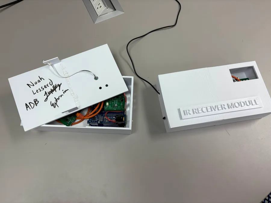
I won’t lay out the entire project requirements in this post, since there were a lot of items. But the short version is that our project goal was to reliably transmit both analog (voice) and digital (temperature) data across 2 battery powered PSoC6 devices. The microphone and speaker amplifiers, and voltage regulators for the batteries won’t be covered in this post. Let’s get onto the fun IR stuff.
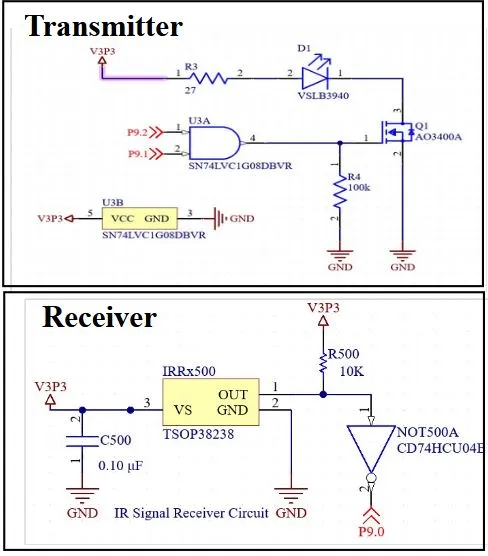
We used a TSOP38238 IR receiver diode and a VSLB3940 IR emitter diode for our optical stack for this project, with one board being the transmitter and one board being the receiver. In hindsight, these were probably odd choices for a high throughput data transmission system, as these devices are mostly built for transmitting on and off signals. But we’ll get into improvements later, when we were just starting this project, we wanted to start with the simplest possible implementation. Additionally, we knew that the TSOP38238 diode was rated for a specific carrier frequency, which we knew would help us control for noise from natural light sources.
We chose UART as the base for our transmission protocol, since it’s designed to be asynchronous. Naively modulating a UART signal along this carrier frequency is pretty easy. We used a PSoC6 GPIO pin to output a 38Khz PWM signal, then we connected that to pin A of AND gate, and connected the transmission line for the UART signal to pin B. So our UART only transmits when the carrier signal is high, effectively modulating our signal! And since the diode is only receiving signals from that specific frequency, this was an effective noise filtering method for our project. We also had to add an inverter to the IR receiver diode to change from active low to active high again before using the received UART input on the receiver device.
However, a carrier frequency doesn’t help when something completely interrupts the beam. When this happens, there will obviously be some lost data, but that was an inevitability in our UDP style design (where the receiver can’t talk back to the transmitter). But there is another issue that can happen when the beam is interrupted. Since we chose 16 bit packets, and UART works by transmitting in 8-byte chunks, we basically transmit then process 2 chunks at a time. Its possible for one of those chunks to be dropped during a beam interruption. Then, when the transmission is over, the receiver is one byte out of sync and will not get a complete end packet, which will lock up its state machine in the waiting phase (see chart below).
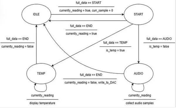
So we need to make some kind of change in order for the beam to be interrupted, and for our device to not lock up. Fortunately, this can be solved with a pretty simple timeout mechanism. If we just compare the time between every 2 packets that the receiver gets, and if the difference is more than a millisecond, just discard the old packet and treat the next one as the new one. This is one of those cool moment when you realize how fast computers are, you waving your hand over the beam is an eternity for them, so its easy for them to just pick up on when an interruption has happened and start over. This ended up working great for us, even if there was no error correction on the data itself, we never had to reset the device to recover from an error in the data stream.
Ok, so now we know how this device achieved its goals, what parts did we mess up on? The biggest thing was the data transmission speed and range. The TSOP38238 diode is limited to a carrier frequency of 38Khz, and a burst length of 10 cycles/burst, or 10 cycles/bit. This means that we could only achieve a UART transmission rate of 3600 baud, which is pretty slow. This doesn’t really matter for the temperature data, but for voice it meant that we were limited to slow transmission speeds. We were able to get it down with some sample averaging and MSB compression, but we really should have chosen a different diode. In the future, a higher speed connection would need either a smarter modulation scheme, a receiver with a shorter minimum burst length (fewer cycles per bit), or a higher carrier frequency.
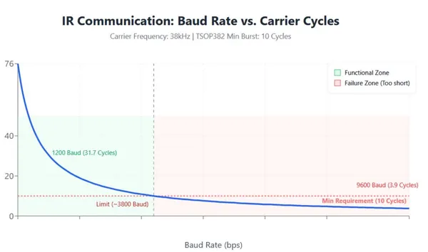
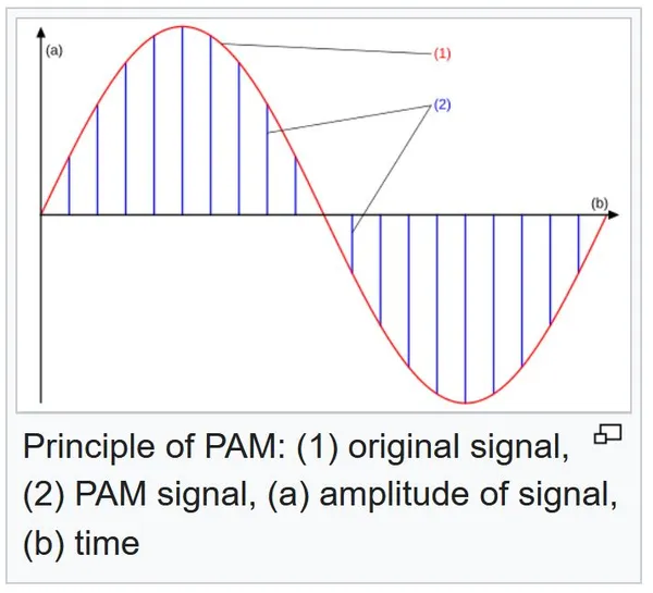
This modulation scheme is something that I’m still learning about, but instead of using binary transmission, aka On-Off Keying (OOK), it seems to be much more efficient to transmit a modified waveform, then decode back into digital data, something like Frequency Shift Keying (FSK) or Pulse Amplitude Modulation (PAM). PAM, for example, would encode data into different levels of brightness, instead of just having every bit be ON/OFF. With 8 levels of brightness, you could extract 3 bits of information from just one ‘pulse’ of light, which would triple our transmission rate. Of course, this would introduce more complexity, needing to have more ADC processing logic as well as being less resistant to noise, but it would be faster.
It also would have been nice to choose a better IR LED to transmit the data with. We chose the VSLB3940 because it was rated as high speed switching, and was designed for consumer data transmission applications. But after some more research (after we had purchased everything of course), it seems like most common LEDs can switch into the MHz range. Our VSLB3940 very well could have that switching speed too, but it is only limited to 100mA, which limited us to range of about 6 feet. With a larger LED, or pulsed LED (or, even a laser!), much longer ranges would be possible. Lenses and some form of beam alignment would also greatly help improve the range.
So overall, this project served its purpose of giving our group hands-on insight into how optical data transmission works, and the challenges that come along with it. Our results fit into the criteria that we had planned to achieve, although now with the advantage of hindsight and some more in depth research into the subject, I do want to revisit this topic in the future and try to get to some more impressive stats, now that I know the basics.